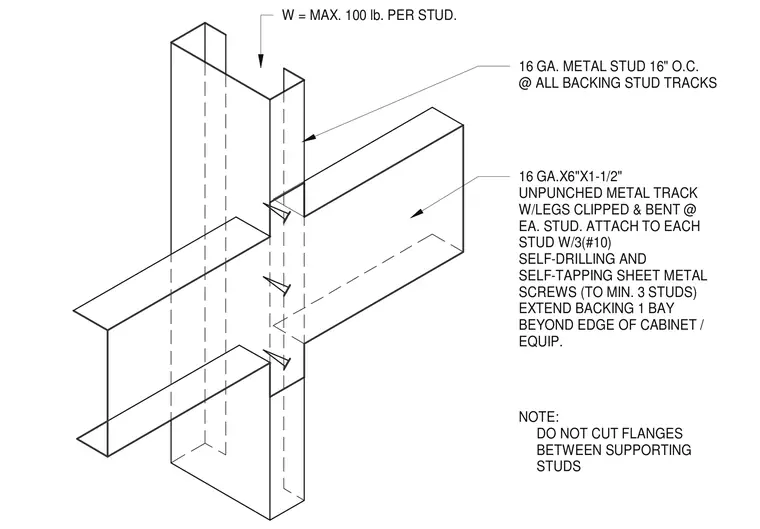
Sixteen-gauge metal studs spaced 16 inches on center receive an unpunched metal track measuring 6 inches by 1-1/2 inches with legs clipped and bent at each stud location. Three number 10 self-drilling and self-tapping sheet metal screws attach the track to each stud across a minimum of three studs. The backing extends one framing bay beyond the edge of the supported cabinet or equipment. Flanges must remain uncut between supporting studs, and the design accommodates a maximum load of 100 pounds per stud.
16 GA. METAL STUD 16" O.C. @ ALL BACKING STUD TRACKS 16 GA.X6"X1-1/2" UNPUNCHED METAL TRACK W/LEGS CLIPPED & BENT @ EA. STUD. ATTACH TO EACH STUD W/3(#10) SELF-DRILLING AND SELF-TAPPING SHEET METAL SCREWS (TO MIN. 3 STUDS) EXTEND BACKING 1 BAY BEYOND EDGE OF CABINET / EQUIP. NOTE: DO NOT CUT FLANGES BETWEEN SUPPORTING STUDS W = MAX. 100 lb. PER STUD.
Members view this detail in full resolution, download the CAD files (SVG, PDF), and can adapt it in the built-in CAD editor — export DXF, DWG, or PDF.
Start membership