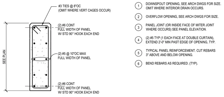
This concrete wall panel section details the internal reinforcement layout including two number six continuous bars with standard ninety degree hooks at each end across the full width of the panel. Two number five bars spaced at ten inches on center maximum run the full width of the panel alongside number three ties spaced at eight inches on center, omitted where vertical bar cages occur. Additional notes specify downspout and overflow opening sizes per architectural drawings, with two number five bars on each face at double curtains extending two feet minimum past the edge of the opening. Rebars are cut three inches above and below openings and bent as required.
1 DOWNSPOUT OPENING, SEE ARCH DWGS FOR SIZE. OMIT WHERE INTERIOR DRAIN OCCURS. OVERFLOW OPENING, SEE ARCH DWGS FOR SIZE. PANEL JOINT (OR INSIDE FACE OF MITER JOINT WHERE OCCURS) SEE PANEL ELEVATION. (2) #5 TYP (1 EACH FACE AT DOUBLE CURTAIN), EXTEND 2'-0" MIN PAST EDGE OF OPENING, TYP. TYPICAL PANEL REINFORCEMENT. CUT REBARS 3" ABOVE AND BELOW OPENING. BEND REBARS AS REQUIRED. (TYP). 2 3 4 5 6 SEE PLAN (2) #5 @ 10"OC MAX FULL WIDTH OF PANEL #3 TIES @ 8"OC (OMIT WHERE VERT CAGES OCCUR) (2) #6 CONT FULL WIDTH OF PANEL W/ STD 90° HOOK EACH END (2) #6 CONT FULL WIDTH OF PANEL W/ STD 90° HOOK EACH END
Members view this detail in full resolution, download the CAD files (SVG, PDF), and can adapt it in the built-in CAD editor — export DXF, DWG, or PDF.
Start membership