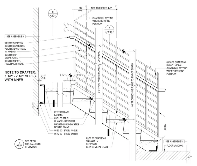
This elevation details a steel stair guardrail and handrail assembly mounted to metal stair stringers. The guardrail features five-eighths inch metal rails and a three-inch by five-eighths inch top bar, positioned three feet six inches above the nosing plane. A handrail is supported by a quarter-inch steel handrail bracket. The guardrail is welded to the steel channel stringer at typical spacings not to exceed four feet. Steel angles and steel embeds anchor the stair assembly at intermediate and floor landings.
05 50 00 5/8" METAL RAILS SEE DETAIL FOR CALLOUTS IN COMMON 05 50 00 GUARDRAIL ALIGN END VERTICAL W/ NOSING 3'-6" FROM NOSING PLANE TO TOP OF GUARD 05 50 00 HANDRAIL 05 50 00 1/4" STL HANDRAIL BRACKET 05 51 00 STEEL CHANNEL STRINGER GUARDRAIL BEYOND WHERE RETURNS PER PLAN 05 50 00 GUARDRAIL WELDED TO STRINGER NOT TO EXCEED 4'-0" TYP EQ 05 51 00 METAL STAIR 05 50 00 GUARDRAIL 3"x5/8" TOP BAR 4" ALIGN A521 1 CLR 0' - 1" SEE ASSEMBLIES SEE ASSEMBLIES FLOOR LANDING 05 12 00 - STEEL EMBED 05 50 00 - STEEL ANGLE 3 1/2" 2 1/2" DASHED LINE INDICATES NOSING PLANE NOTE TO DRAFTER: 1 1/2" - 2 1/2" VERIFY WITH MNFR GUARDRAIL BEYOND WHERE RETURNS PER PLAN 3'-0" FROM NOSING PLANE TO TOP OF RAIL INTERMEDIATE LANDING 8 A521 7 A521
Members view this detail in full resolution, download the CAD files (SVG, PDF), and can adapt it in the built-in CAD editor — export DXF, DWG, or PDF.
Start membership